7 Tips for Switching from Pneumatic to Electric Actuators

Moving from pneumatic to electric actuators is more than replacing an air line with a cable. The change can affect motion control, machine layout, maintenance, and operating costs. A cylinder that moves a light guard may need a very different solution from an actuator positioning a loaded valve every few seconds. The details matter.

Start with the job, not the product catalog. Record the required force, stroke, speed, duty cycle, and mounting space. Watch the machine during a normal shift, if possible. Does it stop often? Does it need precise positioning, or only a firm end stop? These observations help narrow the choices before comparing actuator specifications.

A pneumatic to electric conversion may reduce the need for compressed air at one station, but it also introduces electrical connections and control requirements. Check the available supply voltage, controller compatibility, cable routing, and the surrounding temperature or washdown conditions. Small omissions can become expensive. A connector that fits on paper may be awkward beside a moving machine guard.

The seven tips in this guide cover the practical checks that make a transition more predictable, from sizing and controls to installation and testing. They are not a substitute for reviewing equipment documentation or consulting a qualified engineer when loads and safety functions are involved. And there is room for judgment: real machines rarely behave exactly like a spreadsheet. Allow time to test the selected actuator under actual operating conditions, then adjust the plan if the results disagree with your assumptions. A little doubt is useful.
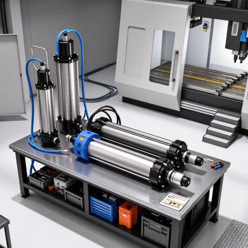
7 Tips for Switching from Pneumatic to Electric Actuators

Audit Compressed-Air Use: DOE Estimates Leaks Waste 20–30% of Output

Before switching from pneumatic to electric actuators, measure what your compressed-air system actually delivers. The U.S. Department of Energy’s Improving Compressed Air System Performance sourcebook estimates that leaks can waste 20–30% of compressor output. That loss may hide in a quiet hiss near a fitting, a hose behind a guard, or equipment left pressurized overnight. A pressure gauge alone will not reveal the full cost.

Tip: Use an ultrasonic leak detector during quiet periods, then tag and repair leaks by location. Log compressor runtime and pressure before and after repairs. Check several shifts; demand can change sharply between production and idle hours. DOE guidance also recommends regular leak surveys, since repairs can degrade or new leaks can appear. Small leaks add up.

Use the audit to compare actuator duty cycles, force requirements, and time spent holding position. Estimate the air consumed per cycle, then compare it with the electrical demand of a suitable replacement. Include wiring, controls, and maintenance in the calculation—not just actuator purchase cost. A leak survey is useful, but it is not a complete conversion study. Some assumptions may be wrong; verify them with measured operating data before changing equipment.
Measure Load, Stroke, Speed, and Duty Cycle Before Sizing Actuators

Before replacing a pneumatic cylinder, measure the real load—not just the part’s weight. Include friction, acceleration, tooling, and any force needed to overcome seals or misalignment. Then record the usable stroke, not the actuator’s full catalog travel. A few millimeters can matter when a fixture has hard stops. The U.S. Department of Energy’s Improving Compressed Air System Performance sourcebook notes that compressed air can account for about 10% of industrial electricity use, and more in some facilities. That figure describes whole systems, not guaranteed savings from one actuator change.

Tip: Measure under working conditions. Log load force, stroke length, and travel time across several cycles. Compare the slowest cycle, not just the best one. Electric actuators may need extra force to accelerate a load, while speed can drop under load. A quick bench test can mislead.

Tip: Count cycles per hour and note dwell time. These determine duty cycle, heat buildup, and motor sizing. Record peak bursts as well as the daily average. A line that runs gently most of the shift may still overheat during a short, rapid sequence. Leave margin, but avoid oversized actuators; that can add cost and reduce control. Recheck the measurements after installation. Real machinery is rarely as tidy as the drawing.

Pneumatic-to-Electric Actuator Sizing: Example Selection Margins

Illustrative comparison of measured application requirements with selected actuator ratings.

The example application requires 450 N of force, a 250 mm stroke, 80 mm/s speed, and a 40% duty cycle. The selected ratings are 600 N, 300 mm, 100 mm/s, and 50%, respectively. Confirm peak and holding loads, actual travel, required motion time, and duty cycle under real operating conditions before final sizing.

Compare Energy and Lifetime Costs Across the Full Operating Cycle

The purchase price tells only a small part of an actuator’s cost. Compare energy use across actual operating cycles: moves per hour, idle time, load, and years in service. The U.S. Department of Energy’s Improving Compressed Air System Performance notes that leaks can waste 20–30% of compressor output in poorly maintained systems.

That is a plant-level figure, not a guaranteed saving from replacing one actuator. Still, it makes leak checks essential before comparing technologies.

Measure the air used per cycle and the compressor’s specific power, then estimate annual electricity costs using local tariffs. For electric actuators, log power during movement and holding; some designs draw little power when stationary, while others may not. Small details matter. Add filters, tubing, valves, lubrication, repairs, and downtime to both lifetime estimates.

DOE guidance on compressed-air leaks supports fixing leaks as a practical efficiency measure, but savings depend on system conditions. I would not assume electric always wins: frequent motion, high holding force, or harsh environments can change the result. A short field trial may expose errors in the spreadsheet. Compare measured costs over the same duty cycle, then include replacement intervals and maintenance labor across the expected service life.

Specify Environmental Protection Using IEC 60529 IP Ratings

When replacing a pneumatic actuator, do not choose an electric model by torque alone. Check the enclosure’s IEC 60529 IP rating against the actual installation: dust, rain, washdown, or occasional flooding. The first digit describes protection from solid objects; the second describes water ingress. For example, IP6X is dust-tight, while IPX5 indicates protection against water jets. Small details matter. A cable gland facing upward can collect water, even when the actuator enclosure has a suitable rating.

Tip: Walk the installation route before specifying the rating. Look for hose spray, fine powder, standing water, and exposed connectors. Check the whole assembly. The actuator, feedback device, plugs, and cable entries should all suit the environment. An IP67 rating covers dust and temporary immersion under defined test conditions; it does not automatically mean the unit tolerates repeated high-pressure washdown.

Avoid assuming that a higher IP number solves every environmental risk. IEC 60529 addresses ingress, not corrosion, chemicals, UV exposure, or temperature limits. Review those separately using site conditions and the equipment documentation. It is easy to over-specify protection based on a worst-case guess, and that can add cost without fixing the real weak point. I would still verify the cable-entry arrangement on site; drawings can miss awkward mounting angles.

Plan Controls, Safety, and Payback Before Commissioning the Conversion

Switching from pneumatic to electric actuators is not a simple device swap. The control plan must match the process: confirm signal type, response time, travel limits, and duty cycle. Check what happens during a power loss. A valve that once failed closed on air pressure may need a separate fail-safe arrangement. Small details matter. The U.S. Department of Energy’s Improving Compressed Air System Performance sourcebook estimates that compressed air systems use about 10% of electricity consumed by U.S. industry. That figure is a useful prompt, not a guaranteed saving for any single conversion.

Tips: Map each actuator’s load and operating frequency before selecting replacements. Verify electrical supply, enclosure rating, feedback signals, and existing interlocks. Test emergency-stop behavior and loss-of-power response with the equipment isolated. Record the old actuator’s cycle time; otherwise, a slower replacement may disrupt a process unnoticed.

Build the payback case from site measurements, not a generic savings claim. Compare compressor energy and leakage costs with actuator power use, installation labor, controls changes, and planned downtime. Include maintenance needs and spare parts in the estimate. During commissioning, test representative loads, alarm states, and repeated cycles, then document the results. A clean first run is encouraging, but it is not proof of long-term reliability. Recheck performance after operators have used the system under normal production conditions.

7 Tips for Switching from Pneumatic to Electric Actuators - Plan Controls, Safety, and Payback Before Commissioning the Conversion
Tip Planning Dimension Conversion Actions Commissioning Checks and Evidence
1. Define the operating requirements Actuator duty, operating frequency, stroke or rotation, load, process conditions, and required response. Record the existing actuator’s operating profile and the valve or damper’s required torque or thrust across its full travel. Confirm that the proposed electric actuator is suitable for the load, duty cycle, ambient conditions, and enclosure requirements. Verify full-stroke operation under representative process conditions. Record travel time, operating current, position, and any overload or temperature alarms.
2. Map controls and communications Control signals, feedback, PLC or DCS logic, interlocks, network interfaces, and wiring routes. Document existing commands and feedback before removal. Specify required discrete or analog signals, position feedback, communication protocol, and how loss of signal or power will be handled. Check cabinet capacity, cable routing, and electrical protection. Test every command and feedback point from the control system. Confirm local and remote modes, indication scaling, interlocks, alarms, and loss-of-communication behavior.
3. Reassess safety and failure behavior Safe state, emergency operation, stored energy, hazardous-area requirements, and personnel exposure. Review the process hazard assessment rather than assuming the electric actuator will fail in the same way as the pneumatic unit. Determine what happens on loss of power or control signal, and specify a spring-return, backup-power, manual-override, or other arrangement only where the risk assessment requires it. Verify the defined safe response using an approved test procedure. Check emergency-stop and interlock functions, manual operation procedures, isolation points, and applicable site electrical and area-classification requirements.
4. Confirm mechanical fit and sizing Mounting interface, shaft or stem connection, available space, alignment, and operating force. Check the valve or damper interface, mounting dimensions, coupling, travel limits, and access for maintenance. Size the actuator using the equipment supplier’s load data and account for the operating conditions and required design margin. Inspect coupling alignment and fasteners. Confirm travel limits, seating or end-stop behavior, and repeatable operation without binding or excessive load indications.
5. Plan the utility and energy transition Compressed-air demand, electrical supply, air-system support equipment, and operating schedule. Identify which air lines, filters, regulators, solenoids, and local air-system components can be retired, and which must remain for other equipment. Check electrical supply capacity and protection. Estimate energy changes from measured or documented operating data; avoid assuming savings from actuator type alone. Record the baseline and post-conversion energy or utility data using the same measurement boundary and operating period. Confirm electrical load, protective-device operation, and that no required pneumatic services were inadvertently isolated.
6. Calculate payback with site data Installed cost, energy, maintenance, downtime, and any changes in operating or inspection requirements. Use a transparent estimate: annual net benefit = avoided annual costs − added annual costs; simple payback = installed project cost ÷ annual net benefit. Include installation, wiring, controls changes, commissioning, training, and ongoing maintenance; show assumptions and uncertainty. Compare actual post-startup costs and maintenance observations with the estimate. Revisit the payback calculation if operating hours, energy prices, or maintenance needs differ from assumptions.
7. Stage the conversion and commissioning Outage window, process dependencies, rollback plan, documentation, training, and acceptance criteria. Convert a representative asset first where practical. Prepare approved isolation and lockout procedures, wiring and control updates, test sheets, spare-parts arrangements, and a rollback plan before the wider installation. Complete and sign off point-to-point, functional, interlock, and operating tests. Update drawings, asset records, maintenance procedures, and operator training materials before returning the equipment to normal service.