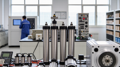
How to Convert Pneumatic to Electric Actuators in 2026
Converting pneumatic equipment to electric actuation in 2026 is a practical way to improve control, but it is not a simple parts swap. On a packaging line, that change may replace an air cylinder, tubing, valves, and a shared compressor with an electric actuator, drive, and control wiring. The right choice depends on stroke, force, speed, duty cycle, washdown exposure, and available space. Small details matter.
The U.S. Department of Energy’s Improving Compressed Air System Performance: A Sourcebook for Industry reports that roughly 80–90% of a compressor’s electrical input can be lost as heat. That figure describes compressor energy conversion, not the guaranteed savings from replacing one actuator. Still, it shows why air use deserves measurement. DOE guidance also emphasizes checking leaks and demand across the system, rather than judging a single cylinder in isolation. A baseline helps.
A reliable pneumatic to electric conversion starts with application data: operating pressure, cycle frequency, load, and air consumption. Then compare actuator sizing, controls, installation effort, and maintenance needs. Electric units can offer precise positioning and simpler local adjustment, but they may introduce new concerns, including motor heating, cabling, and protection from contaminants. The greener option is not automatic. A rushed estimate can mislead. This guide explains how to assess the existing system, select a suitable actuator, plan the retrofit, and verify performance after commissioning—without promising savings before the measurements support them.
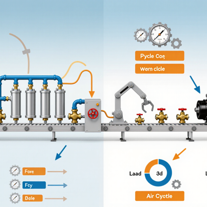
Assess the Existing Pneumatic Actuator and Operating Requirements
Before converting a pneumatic actuator, document how it actually works on the equipment, not just what its nameplate says. Record the valve type, stem travel, mounting pattern, and required opening and closing time. Measure the force or torque needed across the full stroke, especially where the valve tends to stick. Check for air leaks, corrosion, worn linkages, and inconsistent movement. Small leaks matter. They can hide a sluggish valve or an undersized actuator. Note the current air pressure and the actuator’s fail position if supply is lost. Do not assume the existing setup is correctly sized; it may have been adjusted over time.
Then define the operating requirements for the electric replacement. Consider cycle frequency, ambient temperature, moisture, dust, available power, and the control signal from the system. Confirm whether the valve must move to a safe position during a power failure, and specify any position feedback operators need. For example, a valve that moves only a few times each day has different duty needs from one cycling every minute. Verify that the actuator’s torque margin covers breakaway force, not merely normal travel. This step is easy to underestimate. In practice, old valve friction can be uneven, and a single measurement may not tell the whole story. If movement varies, inspect the valve before using that reading to select an actuator.
Select and Size a Suitable Electric Actuator
Start with the valve, not the actuator. Record its type, size, medium, temperature, and maximum differential pressure. Then obtain the valve maker’s torque data for breakaway, running, and end-of-travel conditions. Select an electric actuator whose output covers the highest required torque, using the manufacturer’s stated service factor. Avoid choosing by valve size alone; two similar valves can need very different torque.
Check the operating details, too. Confirm supply voltage, control signal, required opening time, duty cycle, and available space around the mounting point. For outdoor or washdown locations, verify the enclosure rating and ambient-temperature range. A fail-safe requirement may also affect actuator type, wiring, and backup power. The U.S. Department of Energy’s Improving Compressed Air System Performance sourcebook reports that compressed air systems use about 10% of electricity in U.S. manufacturing. That figure is not a guaranteed saving for one conversion, but it supports evaluating compressed-air demand alongside electrical capacity. A missed torque spike can turn a neat retrofit into a stalled valve.
Tips: Photograph the existing nameplate and wiring before removal. Test the valve manually where safe, then compare actual behavior with published torque data. Leave room for adjustment; field conditions are rarely perfect.
Prepare the Valve, Mounting, Power, and Control Interfaces
Before removing the pneumatic actuator, record the valve’s travel, rotation direction, and current fail position. Measure the stem and inspect the bracket for corrosion, cracks, or misalignment. The U.S. Department of Energy’s 2016 Improving Compressed Air System Performance sourcebook reports that poorly maintained facilities may lose 20–30% of compressor capacity through leaks. Check the air line and note existing leakage before disconnection; it may indicate broader maintenance needs. Fit is not proof.
Select an electric actuator using the valve’s required torque at the worst expected pressure, not just its nominal rating. Confirm stem geometry, mounting dimensions, travel stops, and clearance for the enclosure and cables. A drawing can look right while a real adapter binds under load. Check supply voltage, actuator power demand, duty cycle, grounding, and enclosure protection against the installation environment. Then map control signals, feedback, interlocks, and the required safe position after power loss. Test travel and control response before returning the valve to service, and document any mismatch between the wiring diagram and field connections.
Remove the Pneumatic Actuator and Install the Electric Unit
Before removing the pneumatic actuator, isolate and vent the air supply, disconnect power, and verify the valve cannot move unexpectedly.
Mark the existing wiring and note the valve’s normal position. Check the new electric unit’s mounting interface, shaft dimensions, required torque, voltage, control signal, and enclosure rating. ISO 5211 flange compatibility can help confirm mechanical fit, but it does not prove the actuator can turn the valve.
Measure carefully.
Remove the air lines and actuator, then fit the electric unit without forcing the coupling. Set the travel limits and confirm the valve reaches fully open and closed positions. Test local controls and any remote command before returning the valve to service.
Small details matter. The U.S. Department of Energy’s Improving Compressed Air System Performance sourcebook reports that leaks can waste
20–30% of compressor output in typical systems. That figure is system-wide, not a guaranteed saving from replacing one actuator.
Electric units also need suitable power and control wiring; I have seen conversions delayed by overlooked cable routing. A neat installation is not always a successful one. Check operation under the actual process load, and document any mismatch between expected and measured torque.
Configure Controls and Verify Operation, Safety, and Performance
When converting a pneumatic actuator to an electric one, configure the controls around the actual load, not just the old actuator’s size. Check required torque, stroke, travel time, supply voltage, and control signal. Set open and closed limits carefully, then confirm position feedback matches the valve’s movement. An electric actuator may not fail in the same position as a pneumatic unit. Decide how the system should respond to power loss, and provide suitable backup or fail-safe provisions. Isolate energy sources, support the load, and have a qualified person check the electrical connections. Small errors matter.
Tips: Test the actuator with the process safely isolated. Run several full strokes and watch for binding, unexpected movement, or alarms. Compare travel time and current draw with the actuator’s specifications. Check interlocks and emergency-stop behavior, too. Do not guess at limit settings; a little more checking can prevent a valve from being driven hard against its stop.
Record the final settings and test results. Verify operation under realistic load, not only with the valve disconnected. If feedback is inconsistent, inspect wiring, signal scaling, and mechanical coupling before changing control parameters. I have seen commissioning notes miss a simple issue: the displayed position looked correct while the valve stem lagged. Recheck both. Keep the system out of service until its movement, safety response, and control signals behave as intended.