How to Choose Pneumatic Automation Systems?
Choosing a pneumatic automation system is not simply a matter of selecting cylinders, valves, and tubing. It is a production decision. The right system must match speed, force, duty cycle, cleanliness, safety, and maintenance skills. According to the International Federation of Robotics’ World Robotics 2024 report, manufacturers installed 541,302 industrial robots worldwide in 2023. This continued investment shows a clear direction: automation must deliver reliable output, not only impressive specifications. Pneumatic automation remains valuable where fast linear motion, simple control, and rugged operation matter.
Start with the application. Measure the required load, stroke, cycle time, air pressure, and stopping accuracy. A gripper moving small cartons needs different components from a press handling metal parts. Watch the real machine. Listen for air leaks. Check whether moisture reaches the valve manifold. The U.S. Department of Energy notes that compressed-air leaks can waste 20–30% of compressor output in poorly maintained systems. That loss quietly increases operating costs. It also reduces available performance during peak demand.
Energy use deserves careful attention. ISO 4414 provides internationally recognized safety principles for pneumatic systems, but compliance alone does not guarantee efficiency. Compare cylinder sizing, pressure settings, valve response, filtration, and recovery options. Ask suppliers for documented flow rates, service intervals, and operating limits. Field experience matters here. A technically correct design can still fail when technicians cannot source seals or diagnose a faulty sensor quickly. No system is perfect. Calculations may miss dust, temperature changes, or rushed maintenance. Therefore, test the system under realistic production conditions before full deployment. This guide explains how to compare pneumatic automation solutions with evidence, practical judgment, and honest attention to long-term reliability.
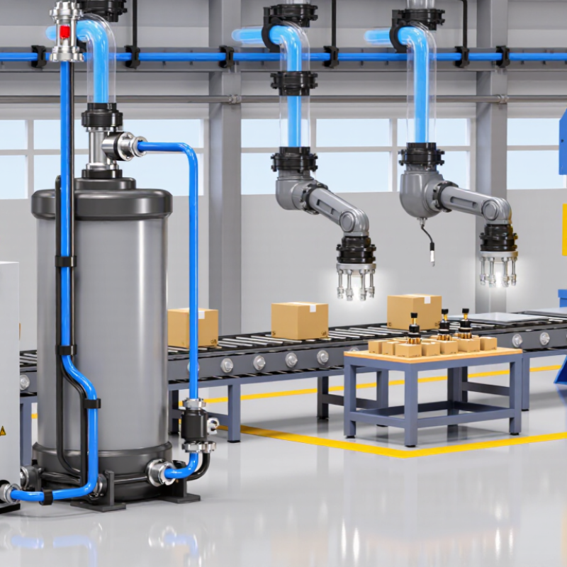
Define Application Needs: Force, Speed, Stroke, Duty Cycle, and IP Rating
How to Choose Pneumatic Automation Systems?
Define the application before comparing pneumatic components. Calculate force from pressure, piston area, friction, and the required safety margin. A cylinder lifting 80 kilograms needs more than 785 newtons of theoretical force. Speed depends on airflow, load, tubing length, and valve response. Specify both extension and retraction speeds. Stroke should match the real movement, not an estimated drawing. Duty cycle matters just as much. Ten cycles per minute creates different heat and wear than continuous operation. The U.S. Department of Energy’s Improving Compressed Air System Performance guide reports that leaks can waste 20–30% of compressor output. Therefore, sizing without checking air consumption can inflate operating costs. Small leaks matter.
Select the IP rating from the actual environment. IEC 60529 defines protection against solids and water, but ratings do not replace material compatibility checks. Washdown areas may require stronger protection than a dusty assembly cell. The International Federation of Robotics reported 541,302 industrial robot installations worldwide in 2023. This figure shows growing automation demand, but it does not prove pneumatics fit every task. A spreadsheet can mislead. Test force, speed, noise, and repeatability under realistic loads. Leave room for pressure variation and maintenance access. My practical preference is conservative sizing, yet excessive margins can slow motion and waste air. Check the compromise.
Size Actuators at 6 bar Using F = pA and Required Safety Factors
How to Choose Pneumatic Automation Systems?
For pneumatic actuator sizing, start with F = pA at 6 bar. Six bar equals 600,000 pascals. A 50 mm bore has an area of about 0.00196 m². Its theoretical extension force is therefore approximately 1,178 N. Real machines produce less. Seal friction, air leakage, tubing losses, and valve restrictions all reduce available force.
Calculate the required load force, then apply a suitable safety factor. For steady vertical loads, 1.5 may be reasonable. Fast motion, impact, or uncertain friction may require 2.0 or more. Do not size from pressure alone. Check the retraction force separately because the piston rod reduces the effective area. Rod buckling also deserves attention on long, unsupported strokes. A larger cylinder is not always better; it can waste air and create harsher stopping forces.
Tips: Confirm 6 bar at the actuator, not only at the compressor. Measure the actual load during startup. Leave room for pressure fluctuation. Check mounting alignment carefully. A small side load can damage seals quickly. I have seen calculations appear correct while the machine still stalled because friction was underestimated. That result is useful feedback, not a calculation failure. Recheck the assumptions, especially when loads are dirty, cold, or changing. Safety factors need evidence, not habit.
How to Choose Pneumatic Automation Systems? - Size Actuators at 6 bar Using F = pA and Required Safety Factors
The reference values below are calculated for a pneumatic cylinder supplied with 6 bar gauge pressure.
The pressure used in the calculation is 0.6 N/mm². The recommended working-load values apply a
1.25 design safety factor to the ideal theoretical force.
Pneumatic Actuator Force Reference at 6 bar Gauge Pressure
Nominal Bore
(mm) |
Representative Rod Diameter
(mm) |
Piston Area
(mm²) |
Annular Area During Retraction
(mm²) |
Theoretical Extension Force
(N) |
Theoretical Retraction Force
(N) |
Recommended Extension Load
SF 1.25 (N) |
Recommended Retraction Load
SF 1.25 (N) |
| 16 |
6 |
201.1 |
172.8 |
120.6 |
103.7 |
96.5 |
82.9 |
| 20 |
8 |
314.2 |
263.9 |
188.5 |
158.3 |
150.8 |
126.6 |
| 25 |
10 |
490.9 |
412.3 |
294.5 |
247.4 |
235.6 |
197.9 |
| 32 |
12 |
804.2 |
691.2 |
482.5 |
414.7 |
386.0 |
331.8 |
| 40 |
16 |
1,256.6 |
1,055.5 |
754.0 |
633.3 |
603.2 |
506.6 |
| 50 |
20 |
1,963.5 |
1,649.3 |
1,178.1 |
989.6 |
942.5 |
791.7 |
| 63 |
20 |
3,117.2 |
2,803.1 |
1,870.3 |
1,681.9 |
1,496.3 |
1,345.5 |
| 80 |
25 |
5,026.5 |
4,535.7 |
3,015.9 |
2,721.4 |
2,412.7 |
2,177.1 |
| 100 |
25 |
7,854.0 |
7,363.1 |
4,712.4 |
4,417.9 |
3,769.9 |
3,534.3 |
Calculation method:
Piston area, A = π × d² ÷ 4
Extension force, Fextend = p × A
Retraction force, Fretract = p × (A − rod area)
Recommended working load = theoretical force ÷ safety factor
At 6 bar gauge pressure: p = 0.6 N/mm²
| Application Condition |
Suggested Minimum Design Factor |
Selection Guidance |
| Stable, guided motion with low acceleration and consistent load |
1.25 |
Suitable for basic force estimation when friction, pressure variation, and alignment are well controlled. |
| General industrial automation with moderate friction or changing loads |
1.5 |
Preferable for typical clamping, pushing, indexing, and handling applications. |
| High acceleration, impact, frequent cycling, or uncertain friction |
2.0 |
Use a larger actuator or higher effective pressure margin after evaluating dynamic loads. |
| Vertical loads, suspended loads, or applications requiring secure holding |
2.0 or higher |
Do not rely on pneumatic pressure alone for load holding; consider mechanical locking, rod locking, or an external safety device. |
Engineering note: The calculated values are ideal theoretical forces and do not include seal friction,
pressure losses, cushioning effects, side loading, speed-related losses, or mechanical transmission losses.
For final actuator selection, verify the actual operating pressure, duty cycle, mounting arrangement, stroke,
rod buckling risk, load guidance, and required stopping or holding performance.
Specify Compressed-Air Quality with ISO 8573-1 Classes and FRL Data
How to Choose Pneumatic Automation Systems?
Specify Compressed-Air Quality with ISO 8573-1 Classes and FRL Data
A pneumatic system should begin with air quality, not cylinder size. ISO 8573-1 classifies particles, water, and oil separately. The notation 3:4:3 describes those limits in that order. Ask the equipment supplier to state the required class clearly. “Clean air” is too vague for reliable design.
I have seen condensation collect inside a transparent filter bowl during humid shifts. That water reached a valve because the drain setting was poorly checked. Specify pressure dew point, particle filtration, and total oil content. Then compare these requirements with the compressor, dryer, and pipe network. A local filter cannot correct every upstream problem.
FRL data also deserves precise attention. Record inlet pressure, regulated pressure, flow rate, filtration rating, port size, and pressure drop. Select the filter for the expected flow, not only the connection size. A small unit may create a hidden pressure loss. Lubrication is not automatically helpful. Some modern actuators require oil-free air, while older components may need controlled lubrication. I once treated lubricator selection as routine, and maintenance later revealed excess oil near sensors. The specification needed more thought. Include drain type, bowl protection, service interval, and gauge accuracy. Test air quality at the point of use, because clean compressor-room air may not remain clean downstream.
Select Valves by Flow Rate, Response Time, Cv, and ISO 5599-1
Choosing pneumatic automation systems starts at the valve, not the catalog cover. In field commissioning, I check the actuator’s air demand, supply pressure, tubing length, and cycle frequency. Flow rate determines whether the cylinder reaches speed under real load. A valve that looks adequate on paper may crawl through a long tube. Measure at operating pressure, not an ideal test condition. Small detail, large effect.
Use Cv as a practical comparison of flow capacity. Higher Cv generally permits more airflow, but it does not guarantee faster motion. Excessive exhaust restriction, undersized fittings, or poor mufflers can become the real bottleneck. Response time matters when a machine indexes parts repeatedly. Check published switching times, then verify them with the actual coil voltage and pilot pressure. I prefer a pressure gauge near the actuator. It exposes delays that software screens often hide. Still, response figures can be incomplete.
ISO 5599-1 helps standardize interface dimensions for certain directional control valves. Confirm the valve size, mounting pattern, port arrangement, and electrical connection before ordering replacements. Compliance with the interface does not prove that the valve meets your flow requirement. Compare Cv, rated flow, response time, and allowable pressure range together. Record temperature and contamination conditions during testing. Air quality changes performance. A clean installation is not always stable, especially when condensate appears after shutdown. Recheck the selection after several production cycles.
Assess Safety, Energy Use, and ISO 11011 Compressed-Air Audit Results
How to Choose Pneumatic Automation Systems?
Assess Safety, Energy Use, and ISO 11011 Compressed-Air Audit Results
Choosing a pneumatic automation system should begin with verified operating conditions, not catalog speed. Check the required force, stroke, cycle rate, and working pressure. A cylinder may perform well during testing, then stall when several machines operate together. That detail matters.
Safety requires more than adding an emergency stop. Review guarded movement, controlled exhaust, pressure regulation, and safe isolation points. Operators should not reach near a moving actuator during adjustment. Test failure conditions, including a sudden pressure loss. Keep records of each test. They become useful evidence during maintenance reviews and safety inspections.
Energy performance depends heavily on the compressed-air network. Request an ISO 11011 assessment covering leaks, pressure drops, supply capacity, storage, and unsuitable air uses. Look for measured flow during production and idle periods. A small leak may sound harmless, yet hundreds of leaks can run continuously. Compare the audit findings with the system’s expected demand before selecting valves, tubing, and compressors.
Do not accept an audit as a perfect answer. Measurements can reflect one shift, one product, or unusual weather. Repeat important readings when production changes. Also question excessive pressure settings. Higher pressure can hide poor sizing while increasing energy use. The better choice is usually the system that meets the process requirement with stable pressure, accessible controls, and documented inspection points. It may not be the fastest option. That is worth considering.